Thursday, July 21, 2016

Plaster Rocks Placed Along the River

This post shows the development of the river area located near the branch line leading to the Atlas Rock Company.  I have used black rubber rock molds and plaster from Woodland Scenics to make various rock castings along the canyon wall.
 
Four Castings Affixed in Place

Dried Castings Waiting to be Fitted Along the Wall

Close-Up View of Castings Along the River Canyon

All Castings in Place and Waiting to be Painted

Sunday, July 3, 2016

Plastercloth Installed Along the Sierra Mainline

A recent post discussed how I built up the terrain along the Sierra's mainline toward Atlas Junction.  This post talks about how I used Woodland Scenics plaster cloth to build a base for the future scenery that will be in this area of the layout.

The first picture shows most of the underlying cardboard mesh covered in the strips of plaster.  Now the contours of the terrain are taking shape and the earthen cut can be visualized easier.

Plaster Cloth Strips Have Been Put in Place
 
I will use this retaining wall and culvert to add interest to the scene.


Retaining Wall and Culvert "Test Fit" in Place

The next two pictures show how I used cuts of styrofoam to build up a small hill to the left of the Sierra tracks.  Once I was happy with the placement of the styrofoam, I covered it with plaster cloth.


The next phase of this project is to make plaster rocks from molds and place them along the shell of the hardened plaster cloth in this area.  I will write about how I accomplished this task in a future post.

Friday, June 17, 2016

Working on the Creek Corner Scene

This week, my work progress has been in regards to the creek area that will be close to the location of the Atlas Rock Company.  I painted the plywood base of the creek bed with black latex paint that I had from a previous project.

Painted Creek Bed
 
Once the paint was dry, I cut out the walls for the canyon from pieces of styrofoam I had on hand.  I also formed the mounded area located across from the wall area with styrofoam as well.  The styrofoam serves as a base for the terrain that will be formed in the area.  I attached the styrofoam pieces with white Elmer's glue.  This glue did not eat through any portion of the styrofoam.

After the glue dried, I used a steak knife to cut the contours of the wall and mound to my desired shape.  The type of styrofoam pieces I had on hand was the bead board type (not ideal for model railroading).  This type makes a huge mess once the cutting and shaping begins.  Fortunately, it does clean up pretty easy with a Shop Vac.

Styrofoam Shapes Glued in Place
The next step was for me to cut strips of Plaster Cloth from Woodland Scenics.  The strips were dipped in water and placed over the styrofoam.  These strips will harden and form a relatively hard shell that still weighs very little.

Woodland Scenics Plaster Cloth
 
Plaster Cloth Being Added to the Styrofoam
 
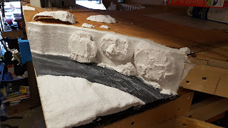
Completion of Plaster Shell
 
I am pleased with the results of this project so far.  I still have a lot of work to do in order to complete the creek scene.  The next portion will consist of me making plaster rocks using Woodland Scenics rock molds and attaching them to the canyon wall.


Layout Rope Lighting

The other day I attached white rope lighting underneath the edge of the new portion of the layout.  The purpose of the rope lighting is to illuminate the walkway areas when the main garage lights are off when running the layout for night time operations.  Attaching the rope lighting to the layout was fairly simple.  I used the plastic clips and screws that were included in the package.  I used two twelve foot lengths of rope lighting from lighting kits I purchased at Lowe's.

Installation of Rope Lighting System

Rope Lights Attached with Fascia Board in Place
 
Rope Lighting Illuminating Walkway

Friday, June 10, 2016

Terrain Building Along the Sierra Right of Way

Once the benchwork for the Merced staging yard was completed and the turnout ladder was outlined, I began to work out the right of way of where the Sierra trackage heading toward Jamestown was going to go.  The Sierra line snakes around the front portion of the layout section as it leaves the Sierra Yard in Oakdale.  The SP Merced trackage runs along the back portion of the layout section and will be hidden by a low profile MDF board.

Turnout Ladder for SP Merced Staging Yard

SP Staging Tracks to Left / Sierra Track to Right


At the edge of the layout in this area, I designed the benchwork so that the terrain could be below the track.  I cut a portion of the 1/2 inch plywood top and some of the 1X3 board with a saber saw.

 
To make the scenery base for the terrain, I planned to make a lattice of cardboard strips.  I cut up an empty cereal box into several small strips.  I just kept cutting until I felt there would be enough strips to cover the terrain.
 
Box of Lucky Charms Cut into Strips
 
Once the strips were cut, I started to attach them to the layout edge with a staple gun.  Some of the strips were curved outward to form a slight hill.  Other areas of the strips were formed to form a flat wall so that I could place a resin culvert and a wooden retaining wall to give the future scenic scene some variety.
 
Lattice Cardboard Attached to Layout Edge

Resin Culvert Placed at Intended Location
 
 
The next step will be to use some Woodland Scenics plaster cloth to cover the cardboard strips to form the base of the terrain.  I will cover this portion of the project in a future post.


Wednesday, June 8, 2016

"L" Shapped Framing Brackets

I really like the idea of having an overhead lighting valence for my model railroad layout.  I like how the lighting valence gives the layout a completed "museum display" look.  The lighting valance allows me to place lighting fixtures directly over the layout so light is not dependent on the normal lights used to illuminate the overall area the layout is set up in.  The other benefit of a lighting valance is that it allows me to have additional storage space above the layout.  Obviously, this will depend on what height the layout is constructed and how tall the backdrop is.

For my layout, I have the top of the 1X3 open grid frame set at five feet.  The 1/2 inch plywood base is on top of that and then I use 1/4 inch cork roadbed prior to laying the Atlas track.  The height of my 1/8 inch MDF backdrop panels are 18 inches tall.  I then use 1X3 boards for the lighting valance framing and 1/2 plywood on top of that.  This puts the top of the valance at approximately seven feet.  I therefore have about two and a half feet of space between the valance and the ceiling of the garage.  This leaves me plenty of room to store boxes and other items above the layout.

A Completed "L" Bracket

 
As mentioned earlier, I used 1X3 boards to make the bracket.  This size is sturdy enough to attach the backdrop to and will support the weight of the 1/2 inch plywood top and the various items I plan to store on top of the layout.  I used a steel "L" bracket purchased at Lowe's to help support and connect the two lengths of 1X3 boards  I used three 3/4 inch carriage bolts, washers and nuts to secure the metal bracket to the wood.  I also attached the metal bracket to the wood with smaller wood screws (see photograph below for details).

Close-up View of the Hardware Used in the Bracket
 
"L" Brackets Installed on One Section of Layout Framing
 
The following photograph shows the completed lighting valence on the main portion of the layout.  The back drop is in place and the bluish glow seen behind the clock is from the illuminated bulbs for the "night lighting."  You can see the amount of space that is left between the top of the lighting valance and the ceiling of the garage.  Of course, I can not actually store anything above this portion of the layout because I need to leave it open so the garage door has somewhere to go when it is in the open position.
 
Completed Section of Layout Benchwork
 
The next two photographs show other sections of the layout where I have placed items on top for storage purposes.
 
Storage Above Stockton & Jamestown Staging Area

Storage Above Merced Staging Area


Tuesday, June 7, 2016

Merced Staging Yard

I have been working on the Merced staging yard where SP trains will arrive and depart during my operation sessions.  Like the other portions of the layout, I have used 1X3 boards to make an open grid and 1/2 inch plywood for the base.  This section is approximately seven and a half feet long and a little over eighteen inches wide.  There will be an additional four feet added to the length when I construct the four foot by for foot corner section of the layout extension.

Merced Staging Yard Benchwork

"L" Frame Supports for Lighting Valence

Lighting Valence Supports Painted Sky Blue

Holes Drilled for Blue Rope Lighting

Turnout Ladder for Five Track Staging Yard
 
Rope Lighting Installed in Lighting Valence
 
 
In the above picture, you can see the void in the benchwork located in the corner of the garage.  This is the next portion of the layout that I will have to construct.  It will be a four foot by four foot corner section that will connect the benchwork seen on the right with the benchwork seen on the left.  On the very right, you can see the door leading out of the garage to the side yard and the "bridge" section connecting Merced staging yard to the main portion of the layout.
 

Saturday, June 4, 2016

Stockton & Jamestown Staging Extension

The construction of the framing and the base of the staging yard extension which represents Stockton for SP trains and Jamestown for Sierra trains is compete.  This section of the layout is a part of the larger layout section used to hold the branch to Atlas Rock Company.  As with my other layout sections, I used 1X3 boards to make an open grid that is approximately twelve feet long and eighteen inches wide.  The grid was topped off with 1/2 inch plywood to form a solid base.

Since this area is going to support multiple tracks to represent each city location (Stockton or Jamestown), I did not want to use individual sections of cork roadbed to support each yard track.  Instead, I chose to use larger cork pads to cover the area much more effectively.

I purchased the cork pads from a big box retailer (Target or Walmart).  They are located in the Office Supply section of the store.  The pads come in a package of four and they each measure twelve inches by twelve inches.

 Quartet Cork Tiles
 
Some Cork Tiles Secured to the Layout
 
I used Elmer's wood glue to fasten the cork pads to the plywood base.
 
Glue Spread on the Plywood Base
 
After the pad was in place, I secured them to the plywood with track spikes.
 
Track Spikes Used to Secure the Cork Pads
 
All Cork Pads in Place
 
With the cork pads in place, I could then attach the 1/8 MDF board I used for the fascia panel.
 
Fascia Panel Installed
 
I then painted the fascia the same tan color I used on the rest of the layout.
 
Partially Painted Fascia Panel
 
Completed Fascia Panel


Friday, June 3, 2016

Passenger Cars for Oakdale Junction

This year, for my birthday, my wife and kids got me four AHM passenger cars.  My wife found them for a pretty good price on eBay.  Anyway, three of them where painted yellow and lettered for the Virginia & Truckee Railroad and the fourth one was painted red and lettered for the Kansas City & Saint Louis Railroad.

AHM Heavyweight Passenger Cars

AHM Passenger Car Components

I used 90% Isopropyl Alcohol to remove the lettering and then painted the car bodies Model Master Olive Drab and the roofs Model Master Classic White.

AHM Passenger Car Shell Prior to Lettering Removal

Letter Removal with Alcohol and Cotton Swab

Repainting of AHM Passenger Car Shells


With the AHM passenger cars repainted to represent Sierra Railroad equipment, the next thing to do is to apply new lettering.  Unfortunately, I am not ready for this step as I can not locate Sierra Railroad passenger car decals.  I have looked several times on the internet and have not been successful.  I can not print my own, as they need to be done in white and a home computer/printer set up can not print in white ink.  I only need three sets to finish my passenger car fleet, but a company would need a larger production run.  I guess I could letter my passenger cars with individual white letter decals or dry transfers, but that seems way to time consuming and the letters would not be spaced our correctly if I did it this way.

Thursday, June 2, 2016

Lighting for East Oakdale Section

As I mentioned in a previous post, I was not able to light this layout section with blue rope lighting to achieve the "night lighting" effect.  My solution was to purchase (Ace Hardware) three individual screw-in light bulb type lighting fixtures.  I then had to figure out how to wire them to a switch and route power to them.

As I am no electrician, I turned to YouTube to see how to do this.  I found a fellow model railroader who did a similar electrical project and filmed how he did it.  Basically, this guy used a grounded electrical cord as a basis for his project.  So, I did the same thing.  I bought an electrical cord, a blue plastic electrical box and a standard wall switch.

I cut off the female end plug of the electrical cord which gave me access to the three inner wires.  I connected one wire to one lead of the light fixtures in series and the other wire to the wall switch and then to the second lead of the light fixtures.  I attached the ground wire to a grounding point.  All of the electrical connections were done with a soldering iron and then covered with heat-shrink tubing.  After the connections were made, I plugged in the male plug of the electrical cord into a power surge outlet.  I flipped the switch on and to my delight; the three light fixtures illuminated with blue light.

*** Special Note ***
 
THIS METHOD IS NOT ACCORDING TO THE ELECTRICAL CODE


Switch and Electrical Box

Electrical Box Installed in Frame


Framing for lighting valance and light fixture installation:

Appropriate Size Hole Drilled in Frame for Light Fixture 

Light Fixture Installed in Frame
 
Light Fixture Fits Flush Against Frame
 
Electrical Cord Connections to Light Fixtures:
 
 
Orange Electrical Cord and Wire Leads for Fixtures
 
Electrical Cord Connected to Terminal Block


Light switch installed in Fascia:
 
Close-up of Light Switch
 
Switch Next to Control Panel
 
Completed framing of East Oakdale:
 
East Oakdale Section with Night Lighting (Behind Clock)